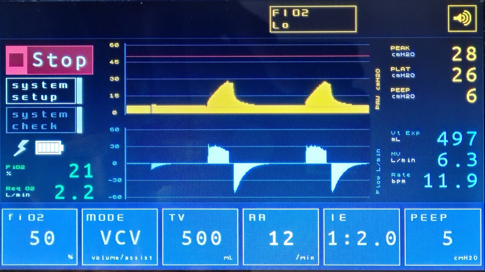
The LycoVent has a LCD touch screen and a rotary encoder with an integral push button to allow the operator to interact with the control system. Additionally, there is an alarm bezel and (internal) alarm sounder to signal an out of range condition or fault.
The touch screen allows the setting of required ventilation parameters by the clinician, displays measured values from the pressure, flow and oxygen sensors and displays alarm codes and tool-tips. Roll over the graphic below to explore the elements of the Main Screen.

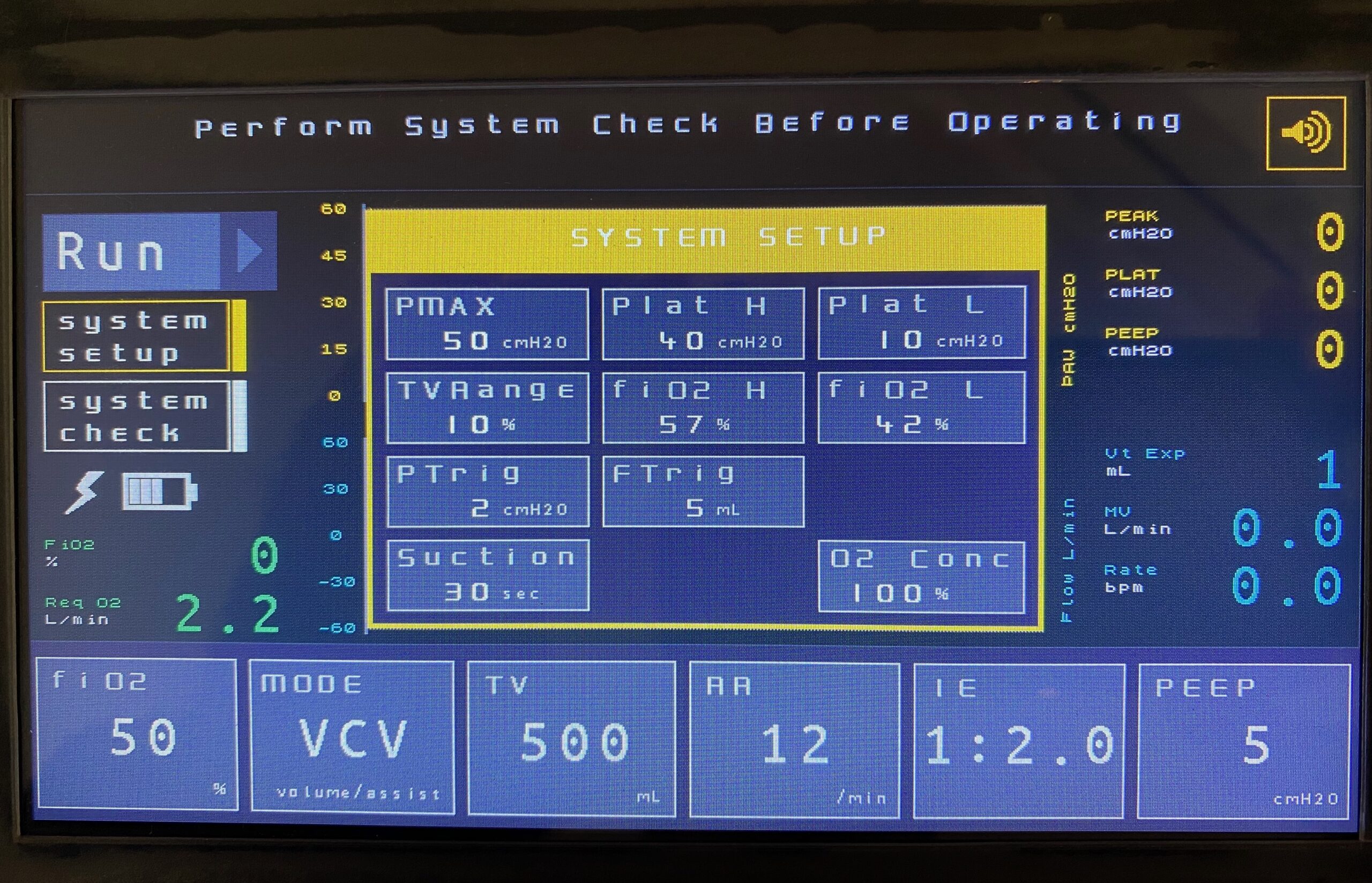
Touching the System Setup on the Main Screen will bring up a secondary pop-up screen where additional system parameters can be set. Roll over the graphic below to explore the elements of the System Setup screen.

Parameter settings are changed by rotating the Encoder Knob below and to the left of the touch screen. Setting a parameter will involve the following steps:
- Select the parameter to be set by touching it on the Touch Screen
- Rotate the Encoder Knob clockwise or anticlockwise to increase or decrease the parameter value respectively
- Press the Encoder Knob to register the parameter value
Full details of user-settable parameters are available under Specifications: User Defined Parameters.
The Alarm Bezel and internal Sounder are provided to alert the operator to a potentially harmful out-of-range conditions. The bezel flash rate and alarm tone will vary depending on the criticality of the alarm. More information on alarms is available here.
